

Power supply voltage regulator structure has a single-way magnetic amplification, dual-way magnetic amplification or DC-DC structure. This structure affects the voltage offset of the +12V, +5V and +3.3V outputs. The DC-DC has the strongest control performance, followed by the dual magnetic amplification, and the worst structure is the single magnetic amplification. The single magnetic amplification, which separates the +3.3V into a separate output, will feature a small coil near the main transformer. And +12V and +5V are controlled by the PWM chip. Therefore +12V high load will have a big impact on +5V output voltage. And there will be two coils in the position of the current regulator structure to give +12V and +5V respectively for current regulation.
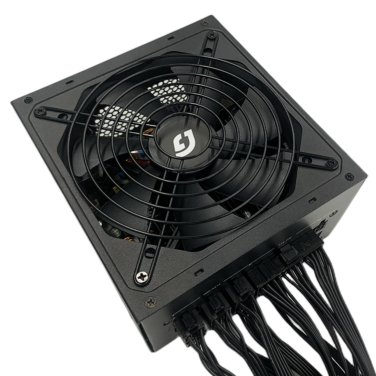
The dual magnetic amplification, which separates +5V and +3.3V, is characterized by two small coils near the main transformer and three large coils corresponding to +12V, +5V, and +3.3V at the location of the current regulator structure. because +5V and +3.3V are independent, the impact on the other two output voltages is reduced at high +12V loads. This is a structure that evolved from single-way magnetic amplification, solving some of the defects that occurred in the use of single-way magnetic amplification.
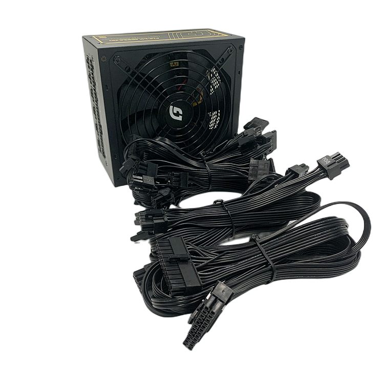
The DC-DC structure, which takes power from +12V and steps it down directly to +5V and +3.3V and then outputs it, so the +12V power rating can be made larger without limit. This structure is the easiest to identify, and there will be a vertical PCB with two coils in the place of the current regulator structure.
I hope this is helpful.